Parameter Models: How CLM Ties it All Together
11/20/2020
IpX - Institute for Process Excellence
 In previous articles, we talked about why Configuration Lifecycle Management (CLM) is an important part of your enterprise portfolio. In one article, we talked about how CLM can enhance the functionality of a PLM tool. In another, we talked about "configurators" are not enough when it comes to front-end sales and CPQ. The disjointed nature of many of those enterprise solutions allows for the creation of invalid configurations or other errors not discovered until further downstream, such as in manufacturing, inspection, or worse, by the customer. To further understand how Configuration Lifecycle Management can be applied across the enterprise and product lifecycle, let's look behind the scenes at how CLM works.
 Figure 1. Different enabling tools and their usage within a product's lifecycle.
A product goes through several phases in its lifecycle. The above graphic shows only one representation of several of the lifecycle states, from concept development through to sustainment. Some companies may also want to consider expanding or compressing the lifecycle phases, including stages like decommissioning, recycling, disposal, or prototyping. Whether you use a phase gate development process, a V-model, or another methodology of your own making, the point is to recognize that different enabling tools are used during each lifecycle phase. There is not a single enabling tool that can be used from a product's conception to its final disposition. In other words, there is no single source of truth.
At any given time in a product's lifecycle, a user may have to reference data in multiple systems to find the true definition of the product. Therefore, if anything were to change during any of the lifecycle phases, each system would have to first be interrogated to understand the impact of the change, then be updated to include the approved changes. An arduous task and one fraught with potential error. So much for automation tools making the change process easier, right?
That is where CLM comes in. Configuration Lifecycle Management is the only tool that tracks all product configuration definitions across all business processes applied throughout all lifecycle phases of the product.
 Figure 2. CLM is the glue that binds enterprise tools together.
Defined Data and Parameters
The specific schema used to communicate data among different software tools is beyond the scope of this article. But one thing is common to all tools: eventually a human must use them and therefore, the data within the tools must be human consumable. This data can be irrespective of product structure, hierarchy, data models, or any other tool specific definitions. In the end, data is data, and that data can be structured and linked in any format necessary for human understanding.
The data could be structured in an as-designed format like an Engineering Bill of Material (EBOM). Or it could be structured based on the methodology used to manufacture the product (MBOM). It could also be structured in the format for make/buy decisions or decomposed and allocated for requirements. Finally, we could also consider data in the form of configuration rules or pricing information which may be structured against features or functions.
Regardless of how the data is structured, if the parameters are linked to the correct objects -- parts, assemblies, items, features, or functions, for example -- then they should be able to be translated among any number of different systems. The key is to not limit one's thinking to legacy data structures. Remember, data is data, therefore parameters could be linked to conceptual objects as fluid as the wind or noise (fitting for a wind turbine example).
These parameters can be used by pre-sales activities (CRM or CPQ), quickly generating valid configurations thereby reducing the need for manual labor to look up reference tables. And while tech sheets and other marketing collateral may be fine to send to a customer, a company should want its sales force to have the latest and greatest information at their fingertips. Reading product specs from a catalog is not as good as getting the data live from a tool such as CLM.
The parameters, such as torque specs, temperature limits, operating conditions, or any other relevant parameter whether physical or conceptual, could also be used during the commissioning, or site installation, of a product. This provides the installation technicians the ability to verify all performance parameters during system startup. Imagine a complex product like a wind turbine. Knowing that every component is acting within specified parameters upon initial startup is paramount to safety and functionality. Where do parameters like that live: PLM, ERP, Excel, or in an engineer's notebook?
The parameters could also be used by maintenance and field support. Replacing a component, especially if the new component is an upgrade, can alter the settings or performance of other components to achieve the same result. Therefore, knowing what parameters may need to be adjusted to compensate for the new component is critical for equipment service and maintenance. These dependencies between parameters can be linked by rules, thus avoiding manual errors or forgetting to adjust a parameter. Automating the parameters through rules also ensures secure logging and tracking of the changes rather than relying on a service technician's notebook.
A Wind Turbine Example
Let's walk through an example of a wind turbine and see how all this fits together.
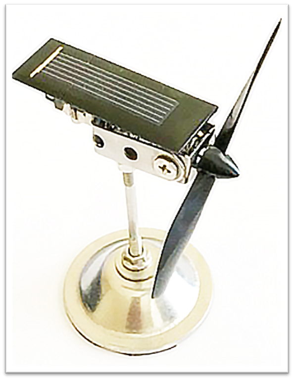
Wind turbines are complex systems. They consist of multiple components: gearbox, generator, nacelle, anemometer, blades, rotor hub, tower, foundation, plus all the components to link to the electric grid, software to monitor performance, and so forth. Even a toy wind turbine comes with a significant number of subsystems as can be seen in the example product hierarchy below:
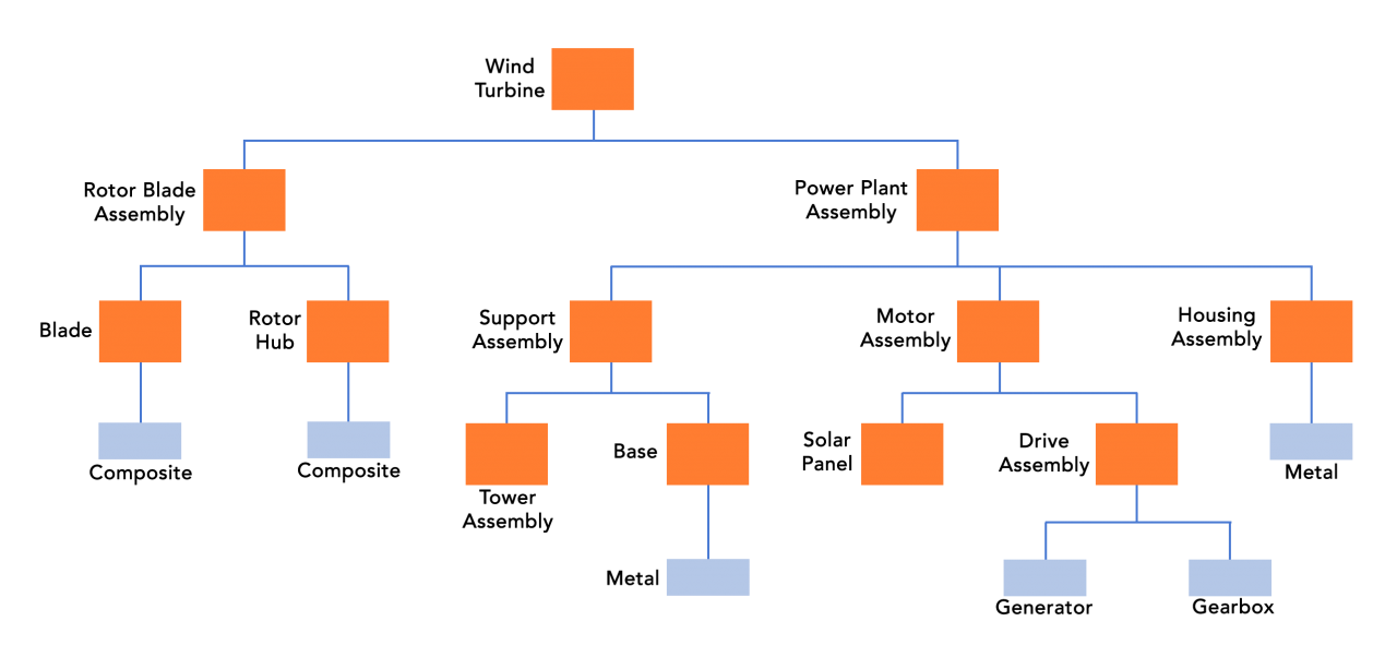 Figure 3. Sample Toy Wind Turbine Product Hierarchy (EBOM).
One way to define each of these components in a typical engineering and manufacturing environment is by linking datasets that define the requirements for proper assembly and performance.
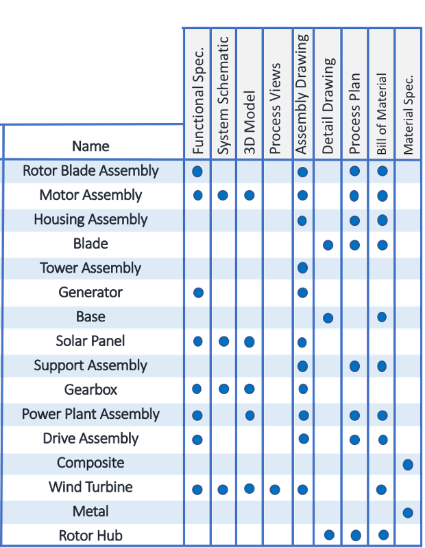 Figure 4. Wind Turbine Components and Their Associated Datasets
Each component may have multiple parameters that drive performance or requirements (See Figure 5 below):
 Figure 5. Each Component may have Multiple Parameters.
Different lifecycle phases of product development may have different parameters (requirements) and the parameters may be better grouped by function rather than component, especially when defining the high-level design basis for the product (See Figure 6 below):'
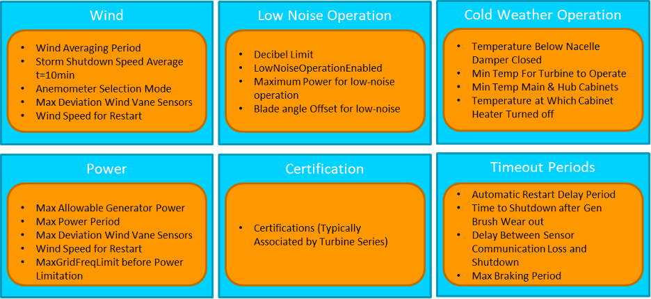 Figure 6. Wind Turbine Functional Parameters
And we cannot forget that many parameters are defined by certain constraints or limitations. These constraints are often categorized or classified by the owning organization of the constraint, such as an external governance of environmental laws (See Figure 7 below):
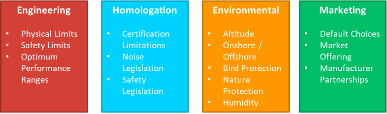 Figure 7. Parameter constraints and limitations as defined by the owning organization
How CLM Ties it All Together
As you can see, requirements come in all shapes and sizes, and they need to be consumed by users in a variety of ways. The EBOM example, which is typically the domain of PLM, links a product hierarchy structure with defining datasets, but does not adequately work for users who must view requirements (parameters) from a functional or governance point of view. And, if all of the different variations of operating parameters were to be listed on an engineering drawing for every possible combination of location, temperature, humidity, manufacturer, supplier, etc., the drawing would be so full of text it would not be usable. Clearly, engineering drawings and PLM are not sufficient.
Some of those parameters can exist inside of CRM or ERP instead of PLM, but that brings us back to the problem of no single source of truth. Users would have to query multiple systems to get a complete understanding of a product's requirements and to determine the full extent of the impact of the change. CLM, on the other hand, with its own set of rules and ability to structure those rules in multiple ways, is the glue that ties these systems together. The image below shows one such example of how parameters could be structured and viewed for our wind turbine example:
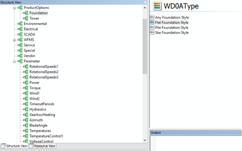 Figure 8. An example of a parameter structure for a theoretical wind turbine.
Conclusion
Purpose-built systems like PLM, CRM, and ERP are fantastic and are a crucial aspect in creating an efficient business infrastructure. But, because each one is built for a specific purpose, and while they each excel at the purpose they were designed for, they do not do well when shoe-horned into managing or modeling other types of data, parameters or workflows across all functions.
CLM is unique with respect to that it does not rely on physical items to create structure and therefore remains consistent with every part change or dataset revision. CLM works on a feature level, and parameters may be structured independent of the physical product structure. CLM goes beyond the engineering and part-driven world, focusing on and specialized for modeling across all functions of an Enterprise. The parameters defined in CLM can then be linked (integrated) to each of the purpose-built systems - PLM, ERP, MES - to create a holistic view of the product, define the single source of truth, and structured in a way that is useful for human consumption that persists beyond any single part or dataset change.
View PDF
